Electrics behind the centre console ...
9 September 2019
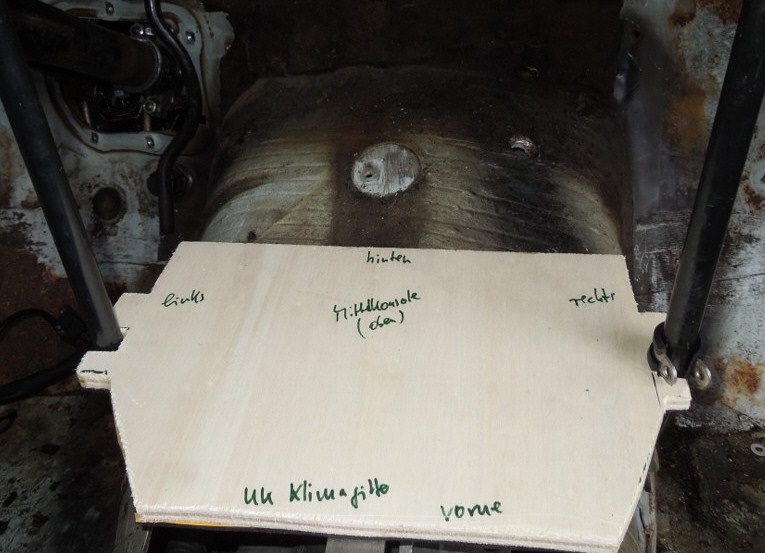
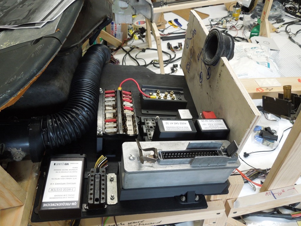
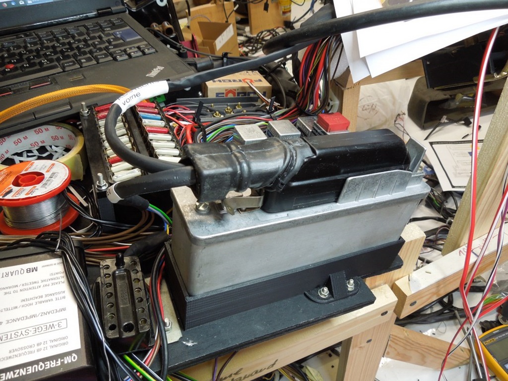
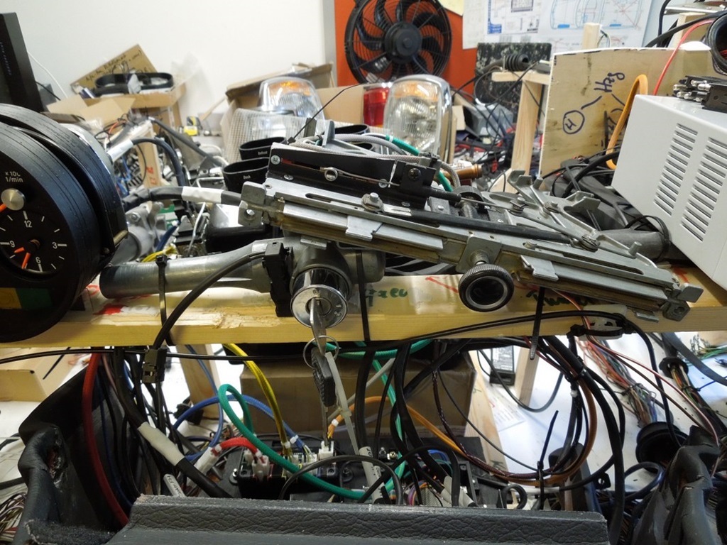
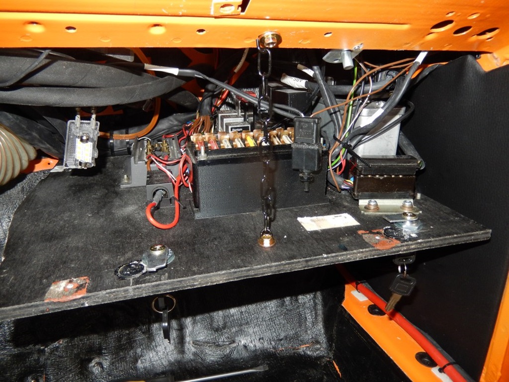
As mentioned elsewhere, most of the electrical components will be installed behind the glove compartment. However, not all will fit there. With the new aircon unit, I do have some space behind the - modified - centre console.
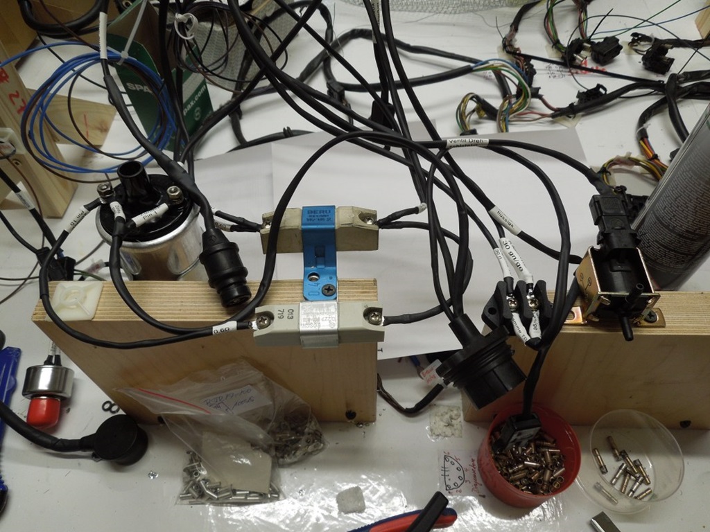
So during the prototype phase, I cut a plywood plate in shape, so it a) fits behind the console and b) can be fixed with the two bars on the left and right.
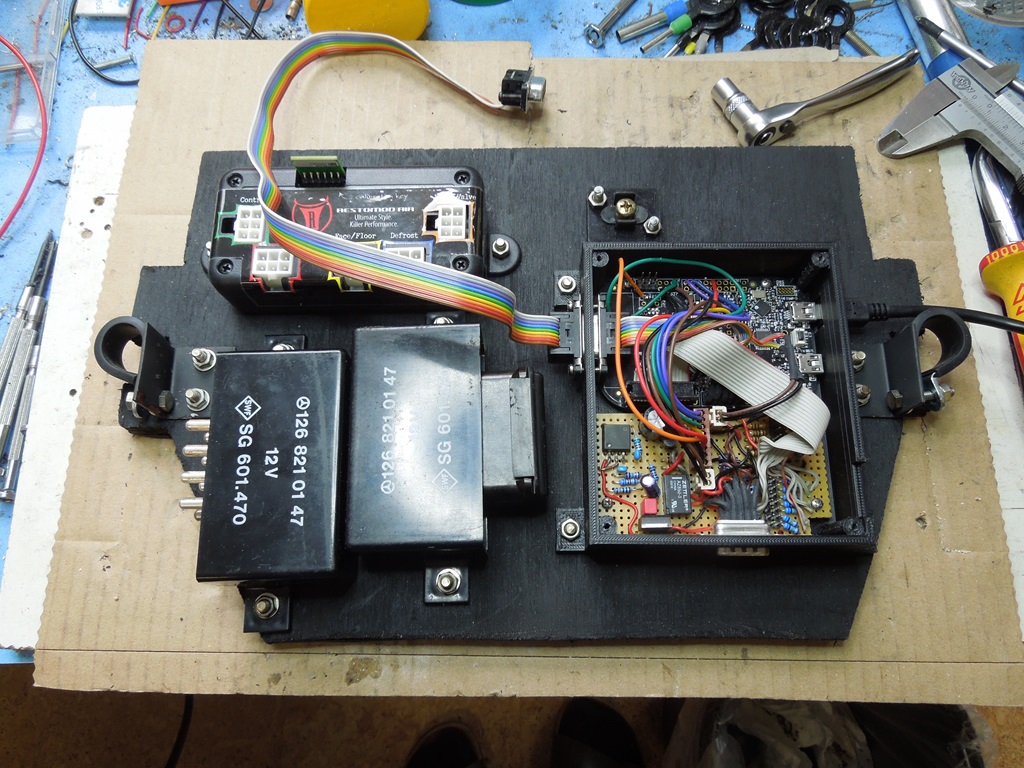
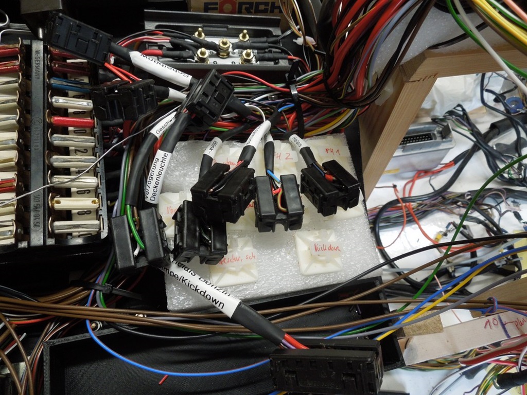
I painted it black and started to fix the parts:
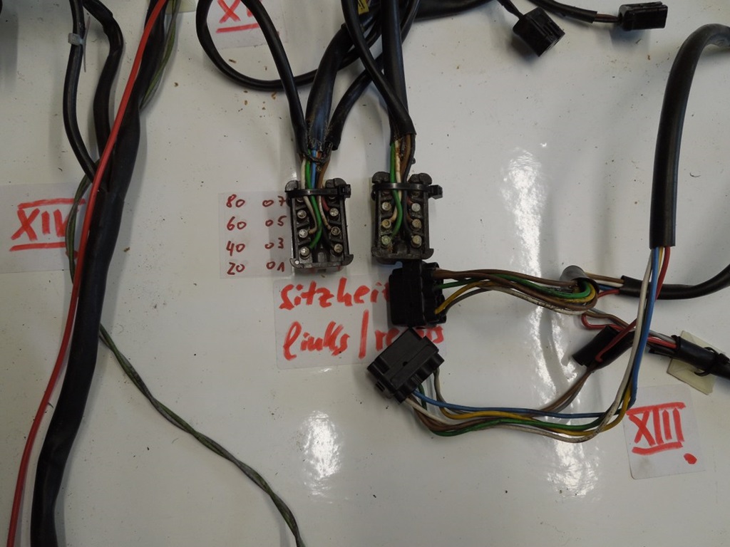
- front left, the two relais for the seat heating (close to the switches)
- front right, my electronics for the gear display, the ashtray display; it also provides +5V for the USB socket
- back left: the control unit of the aircon unit
- back right: my selfmade connector "58d" (originally fitted to the heater box in the R107)
Design of a completely new harness ...
14 September 2019
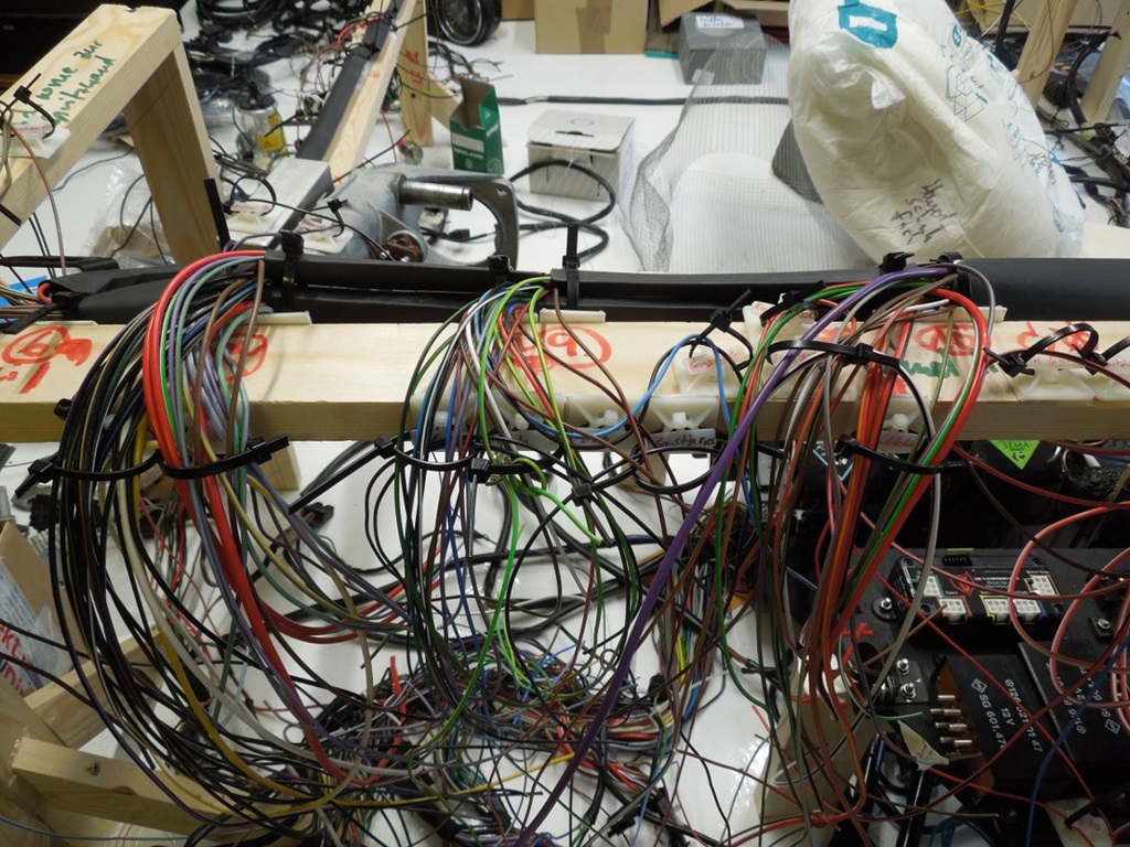
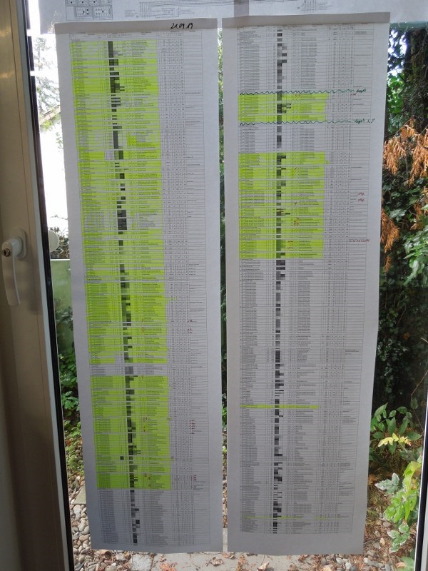
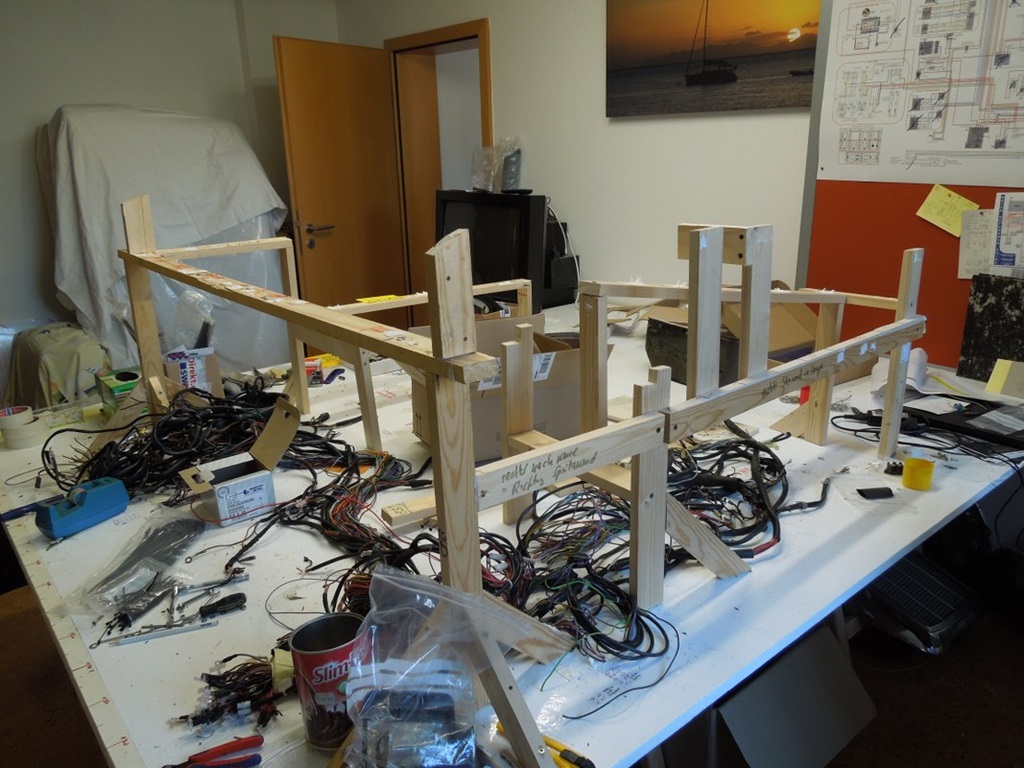
As cables get brittle with the years (at least 37 years), it was clear to me, that I have to make a completely new harness. Also all the changes require additional wiring, that has to be integrated.
While I'm at it, I can also reroute some wiring to make life easier. So what were the steps?
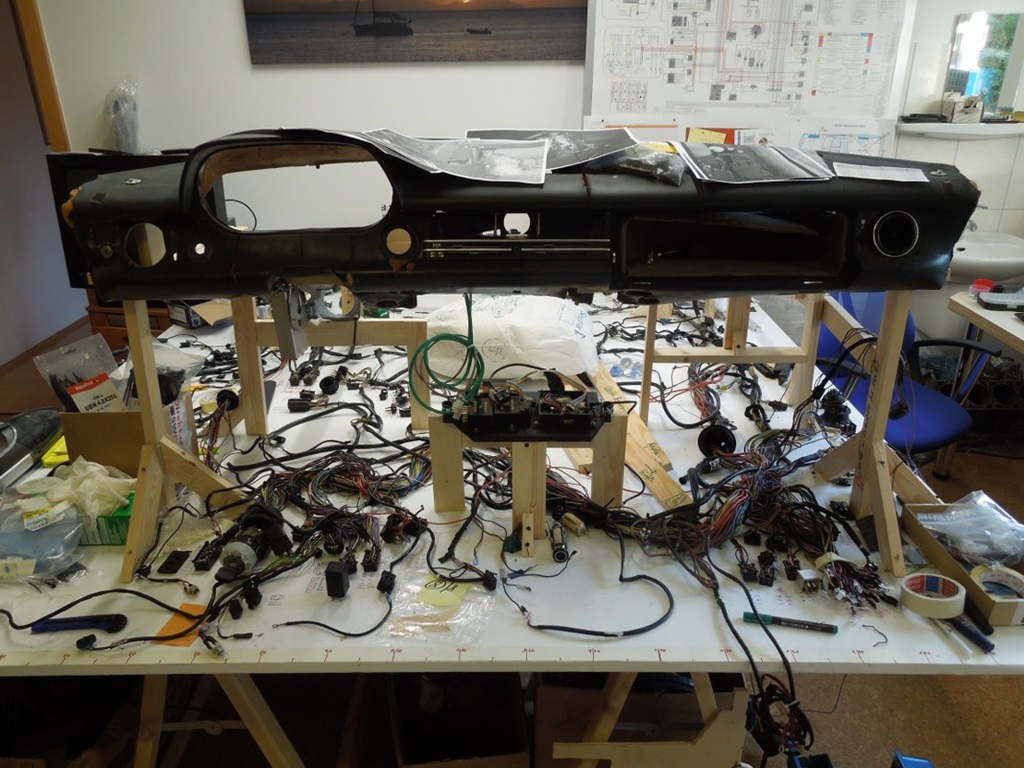
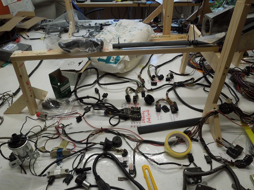
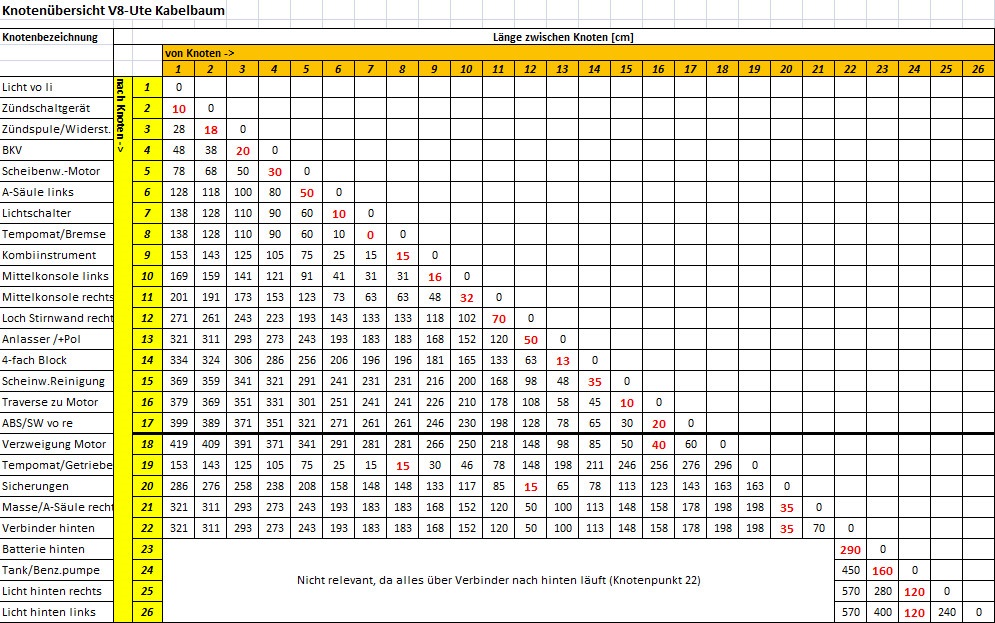
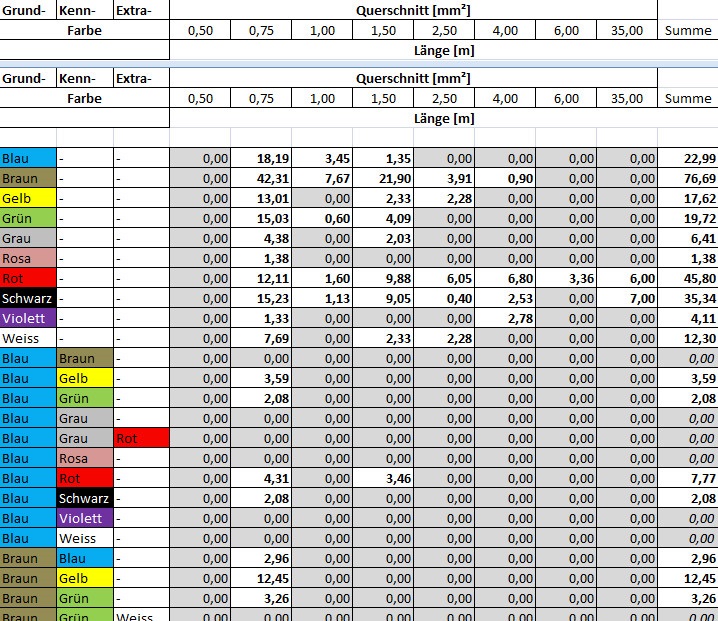
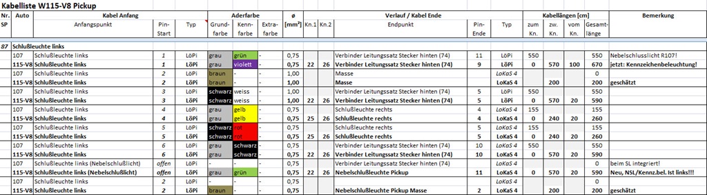
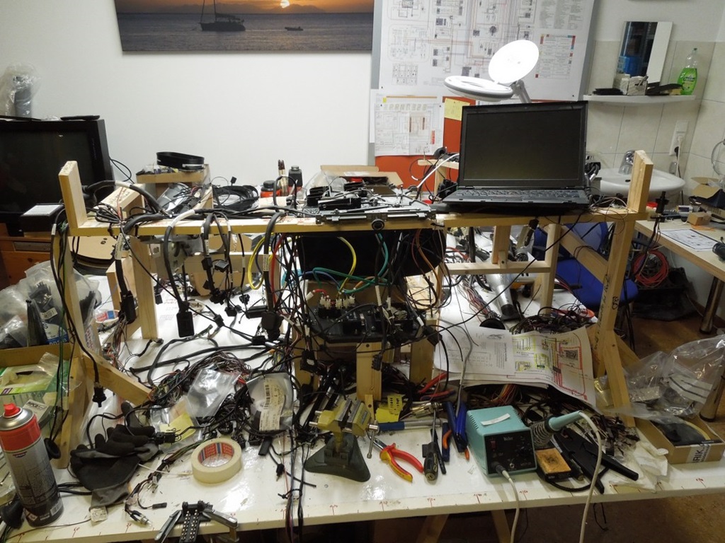
1. The basis was the SL-harness (R107), which I laid out on a big table. EVERY single cable in there was put into an Excel-sheet, with colour, length, diametre, from where to where, etc.
2. All additional wiring was designed, e. g. the electrical fan, seat heating, etc.
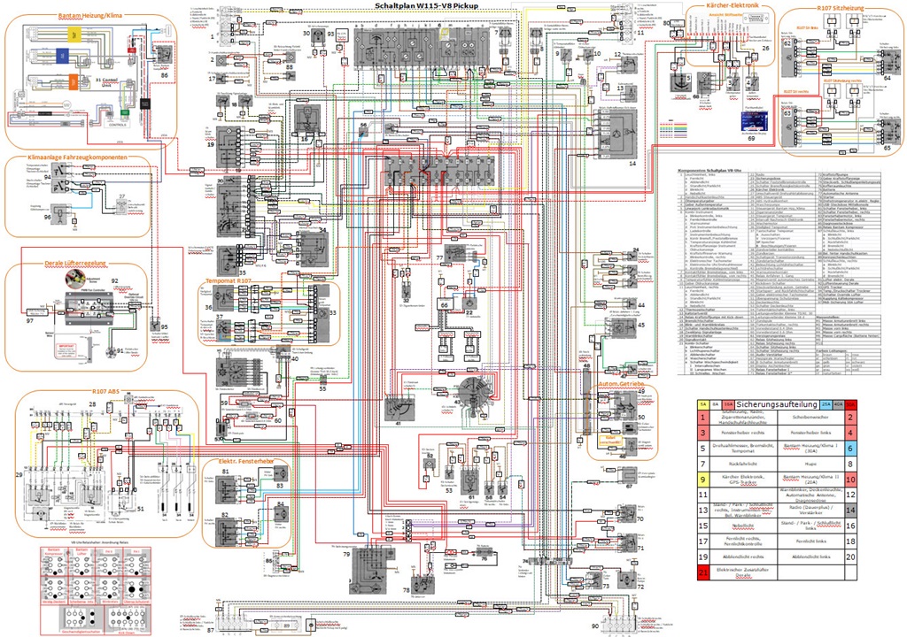
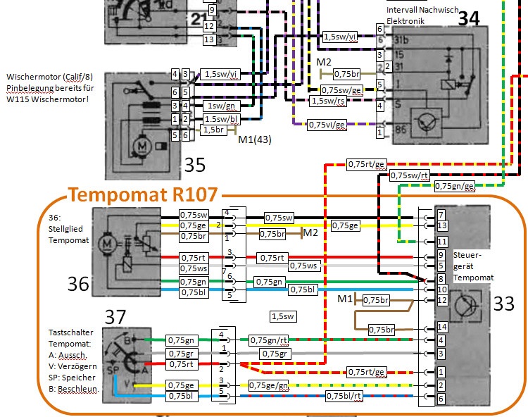
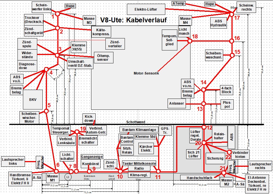
3. A COMPLETE wiring diagram (colour!) was drawn with ALL cables ever being in that car. This also integrates "extras" like ABS, seat heating, cruise control, …
4. The layout in the car was designed with all nodes
So all in all it was a work of months (I don't count the hours anymore), there are 344 single cables with a total length of 547 metres …
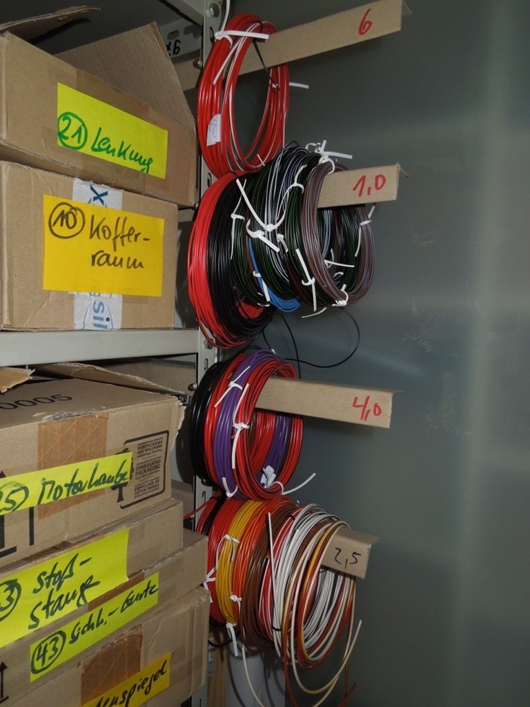
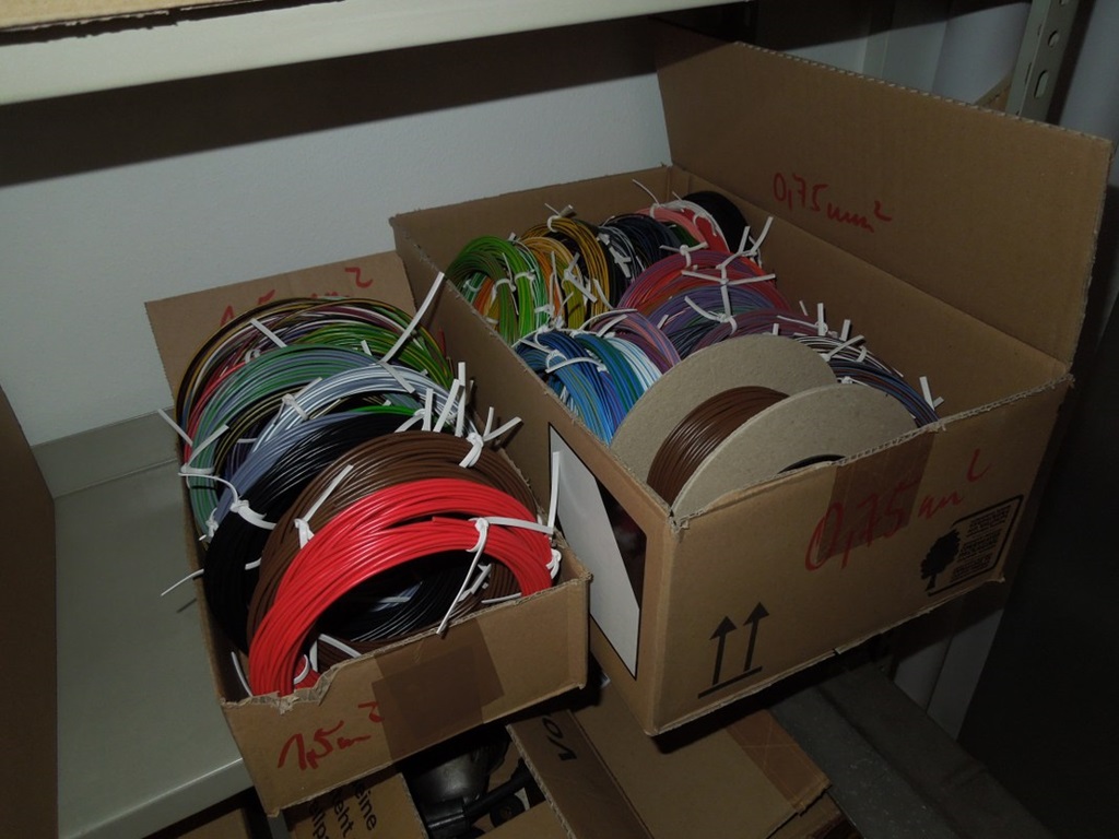
Next step is to order the cables … ;-)
New cable delivery arrived ...
As soon as I have some time, the wiring "fun" can start ...
21 September 2019
Electrics behind the glove compartment ...
22 September 2019
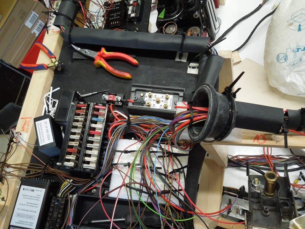
As mentioned in other areas, most of the electrical Installation will be concentrated behind the glove compartment. A wooden plate that can be easily folded down into the passenger's leg area, so fault finding should be easier.
Intensive mockup and measurement has been done when the car was still here, so now it is finished. It will comprise the following:
- ABS control unit with 3D-printed holder for it
- Relais holder with ALL relais of the car
- R107 fuse box with 3D-printed holder for it
- Crossover for the loudspeakers Right
- PWM control unit for the electric fan
(including 50A fuse) - Connector for the rear harness
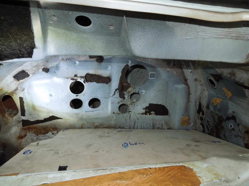
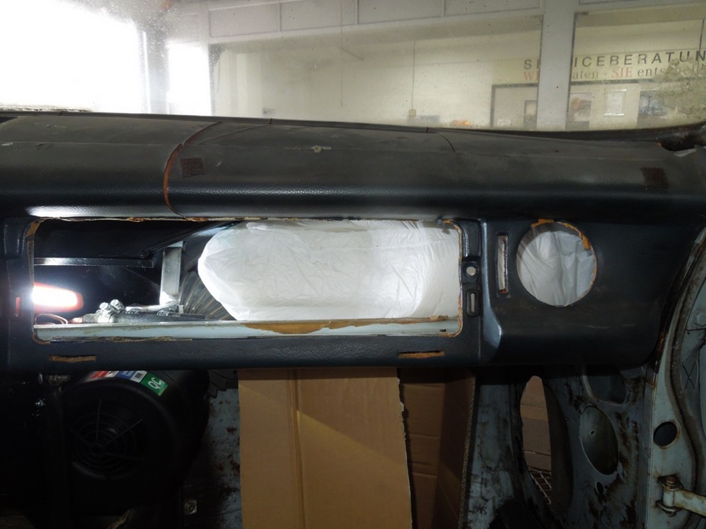
How did I know how much space there is? When the hoses, glove compartment and air vent were in, I bought those packaging "bags", that you put into a box, they inflate and take the shape of the stuff inside the box. So I quickly put it behind the glove compartment and I had the shape of the volume ... see photos:
Wiring fun starts ...
18 October 2019
Having done all the prep work, I finally started this week pulling cables in my "3D-model". What an amount of work! So far four full days and I have pulled approx 70% of the cables … that means pulling only, no connections or soldering (except the fuses box)!
I routed shrinking hoses all the way and tried to label everything, so that after the cable pulling I can start easily with the connectors etc. … New rubber sealings for the fire wall are included too.
The area behind the glove compartment starts getting full; the relais holder is temporarily replaced with a foam element, where I collect all cables going to the relais.
Father's little helper ;-) ...
28 October 2019
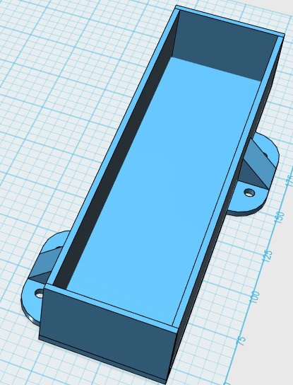
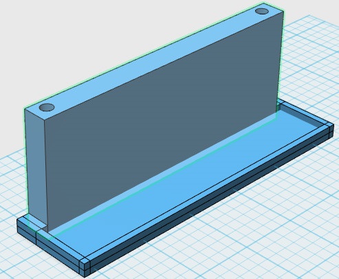
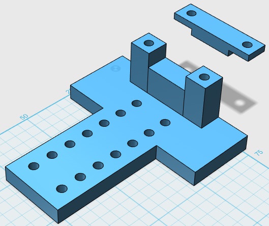
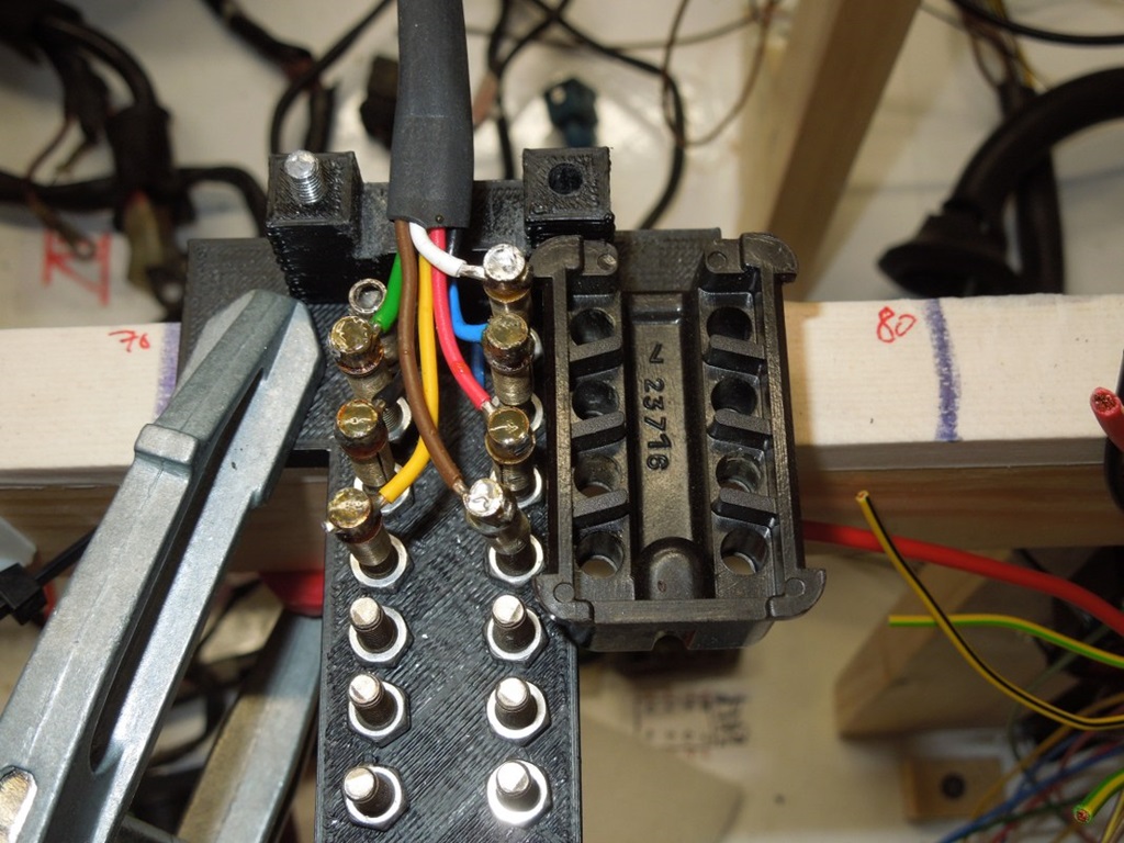
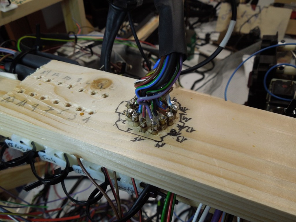
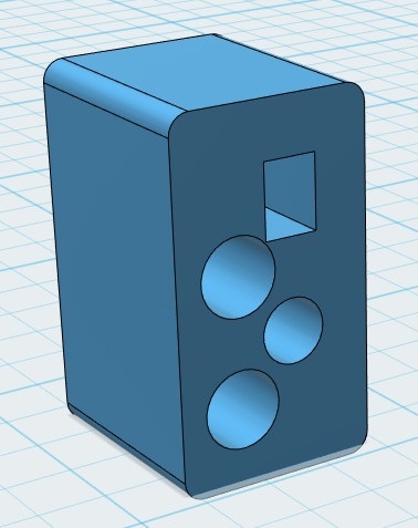
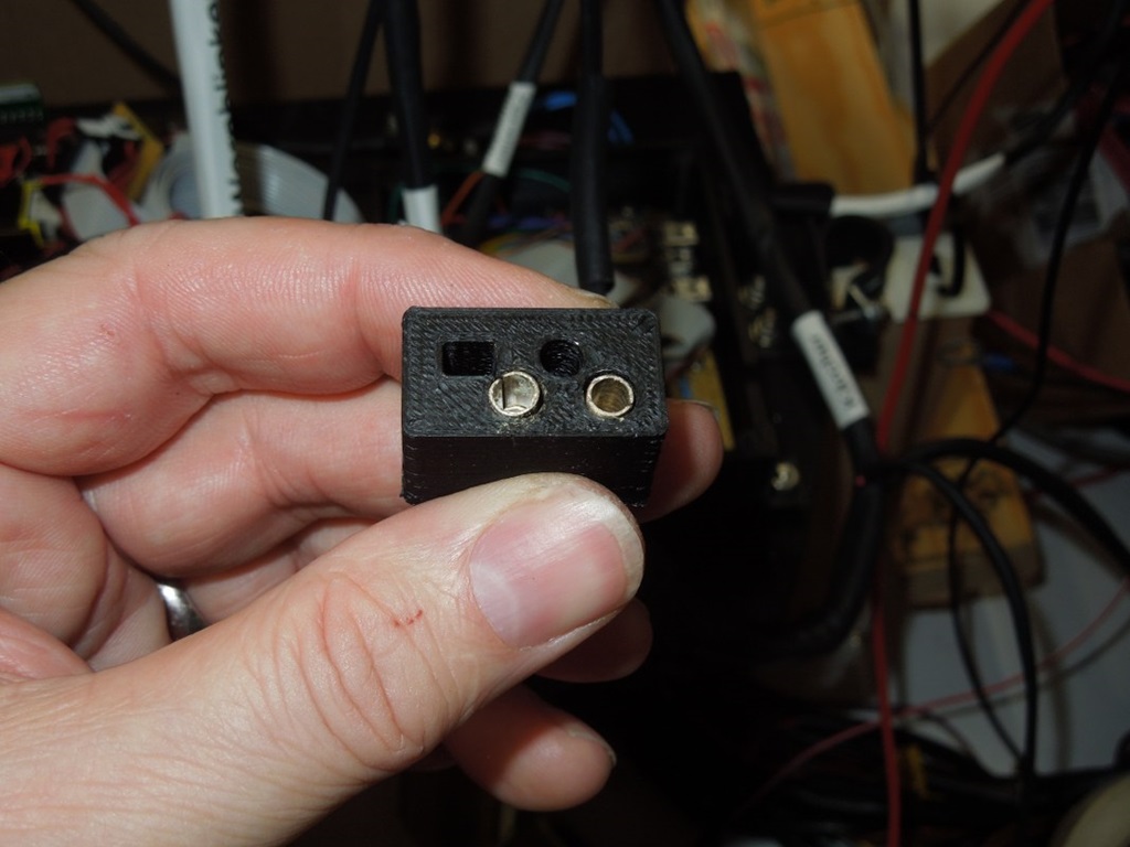
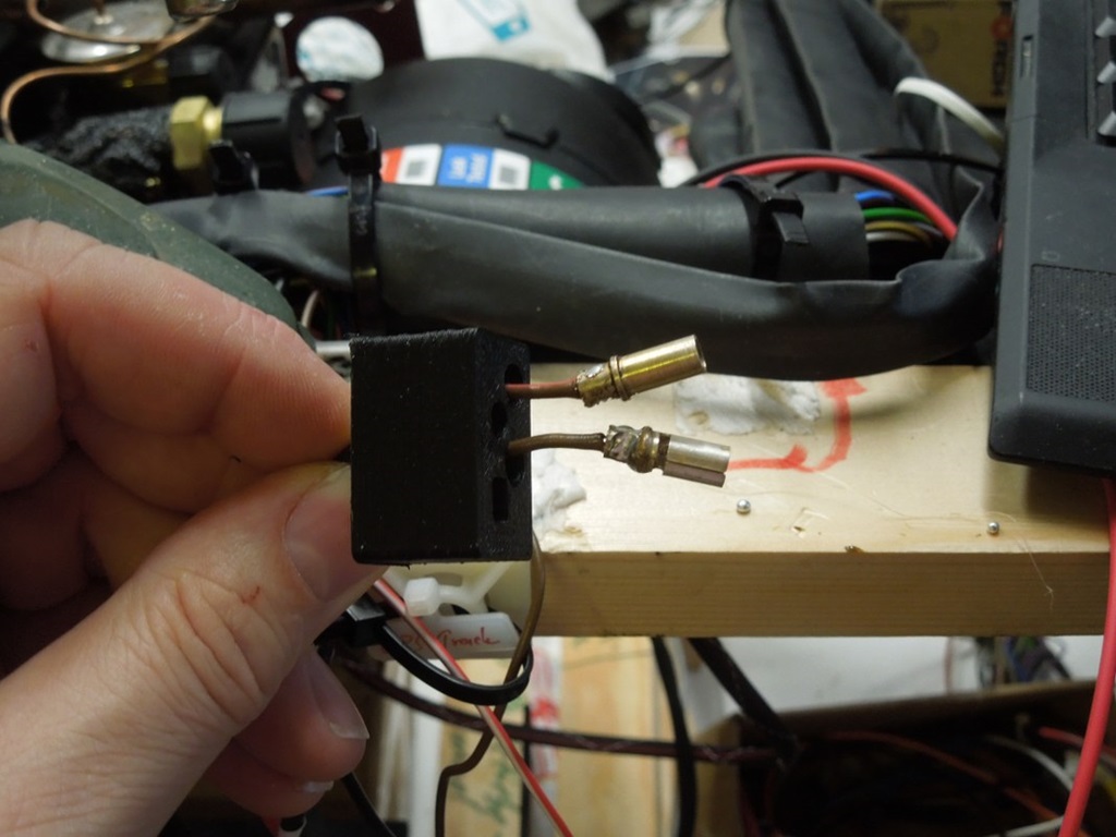
As I am doing this the first time, I thought about a little tool to make life easier when soldering the sockets. I took the average distance between the Pins (they're actually different, depending on the number of Pins) and printed that little tool. You can squeeze the cable in it, put the Pins on M4 screws and then easily pull and solder the wires …
Today I used it the first time and it worked well.
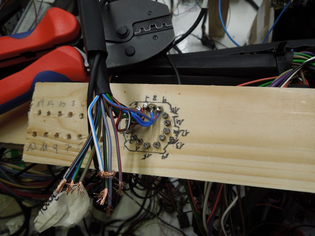
Edit: For the male Version (e. g. connector to the back of the car) I used my tool, put it on a soft piece of wood, stood on it so I could see the marks of the screws on the wood. Drilled 4mm holes in the wood and done.


First wiring & connecting done ...
1 November 2019
The first wiring and connecting is done now. MUCH more work than expected; I spent already full 4 days on it and it is still below 20% (I guess).
According to the wiring diagram I started making connections. On top of that the following was on the list:
- Shrinking hoses (in different sizes) on all cables
- Cables to the motor (heat!) get an additional insulation hose
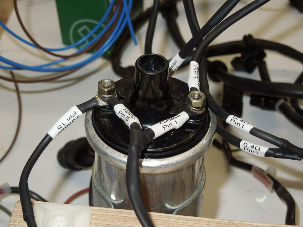
- ALL cables will be labeled properly; I use a Brother shrinking hose, where I can print on. This should make connecting in the car and fault finding much easier
Even little bits and pieces are labeled, e. g. pins 1 and 15 of the ignition coil … to avoid future questions like "where has it been on?" and the "follow-the-cable-to-find-out-where-it-comes-from" ;-)
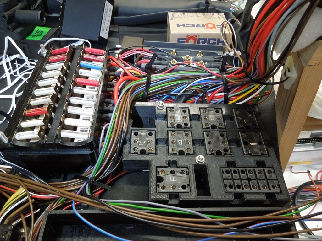
Relais frame connected ...
2 November 2019
Two days work: now all connectors are soldered for ALL relais on the 3d-printed frame. Had to be very careful with the pin assignments, e. g. soldering upside down etc.
Those 6-pin connectors are from a W126 fuse box; they click from underneath into the frame. Was a tight squeeze with this frame and the fuse holder and all the cables, but now it fits.
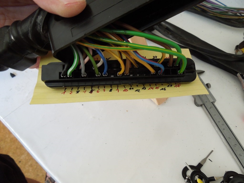
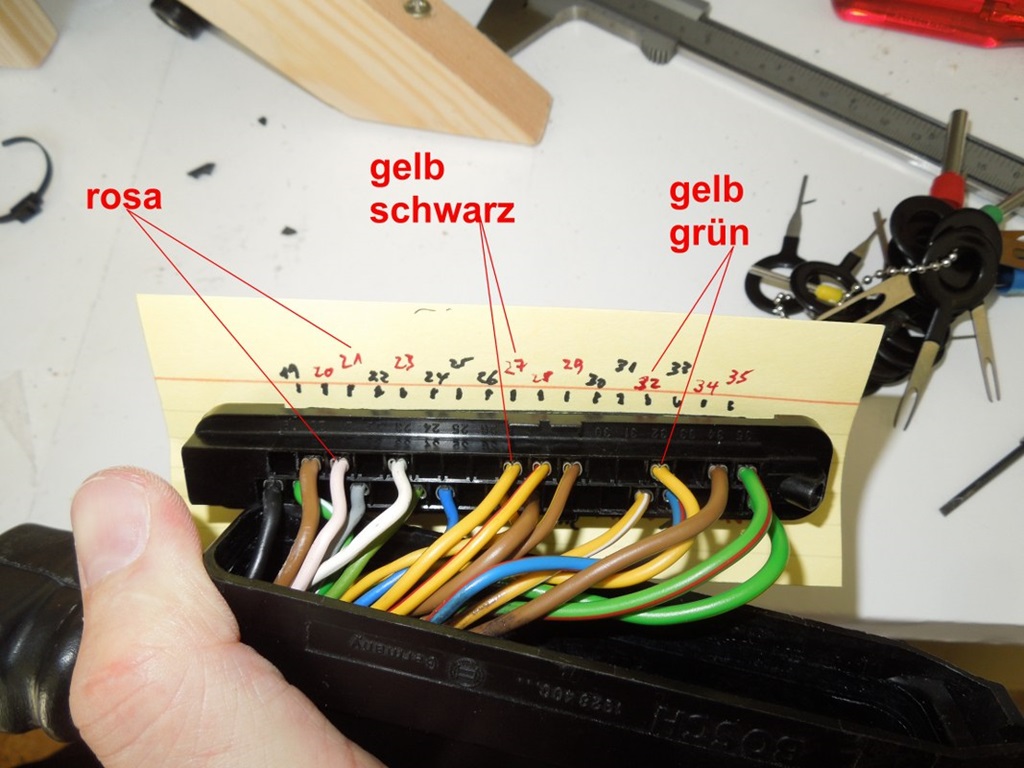
Cluster Connector ...
10 November 2019
Little progress with the harness ... it's a lot of work along the dashboard. Electric windows, seat heating, hazard lights, cigarette lighter, etc. are done.
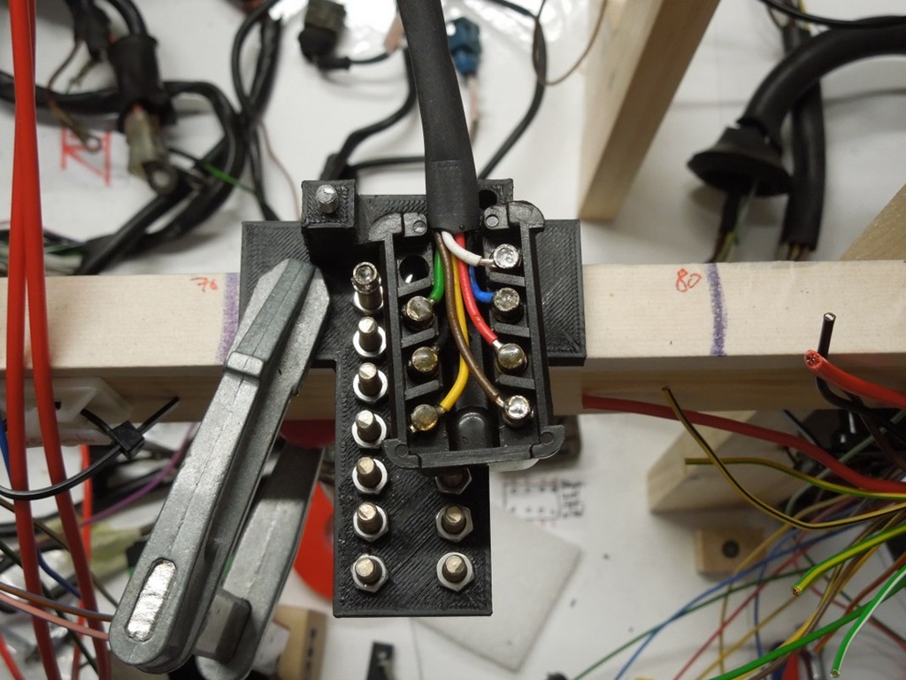
Today I did the cluster … here's the way I did it ...
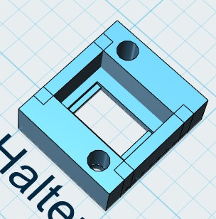
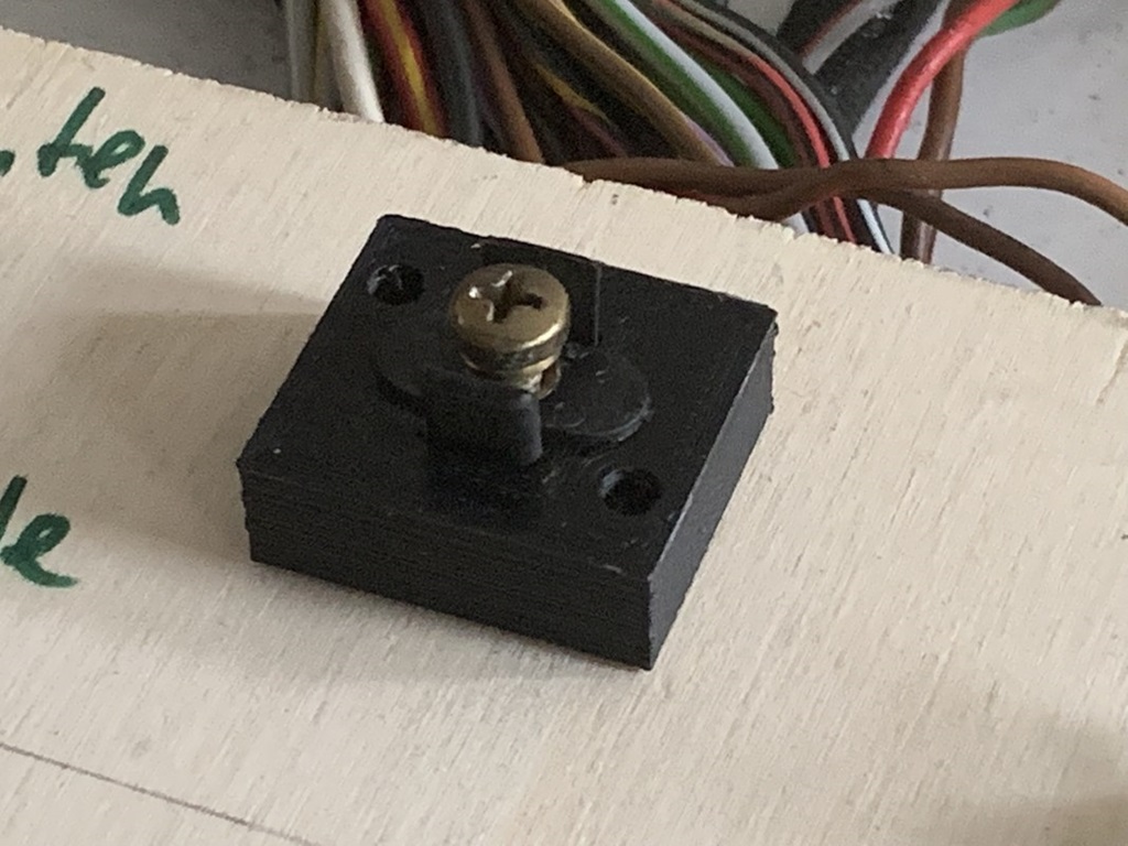
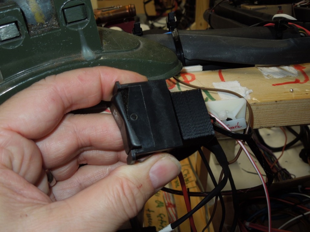
Connector for Interior Light Switch ...
12 November 2019
Unfortunately I didn't have the connector for the interior light switch, I couldn't find the number either. The switch itself is from a W126 or a R107, but I didn't have the coupling.
So I designed it myself, as I need two of them. One for the interior light, the other one for the electric fan override. Here's the result!
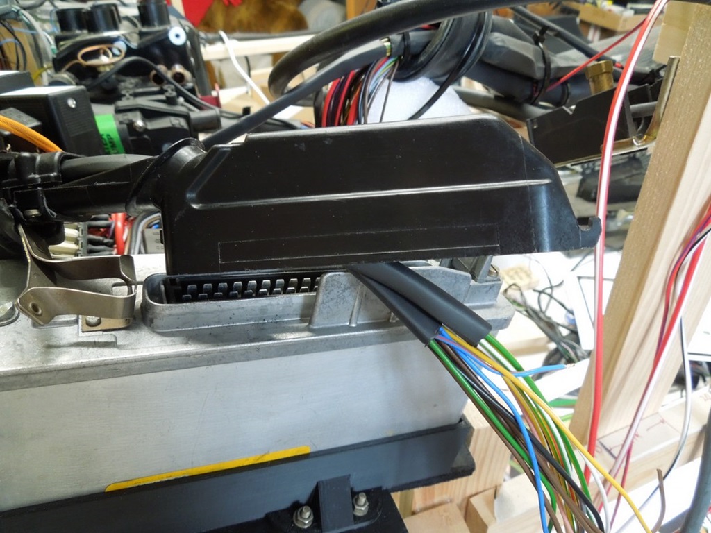
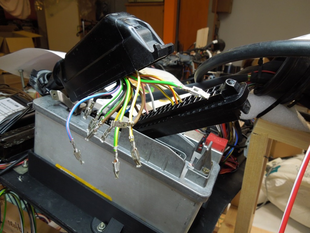
Rewiring of the ABS plug ...
14 February 2020
After three months I continued the harness. One "special" challenge was the plug for the ABS control unit. I was determined to change all the wires, so I had to open it carefully. The shrinking hose I had to cut, but because it is no longer in the foot area (water!), that's not an issue any more.
I carefully checked my wiring diagram and took lots of photos, incl. the pin assignments. After I crimped all cables, I - again - took the multimetre and checked the connections into the car … should be ok!

Wiring finished ...
17 February 2020
I couldn't actually believe it on the weekend: I finished the harness ... I was nearly done in November, when I stopped, but now all cables are done. The modern Aircon is connected (and it works), electric antenna done and the - thicker - cables to the starter motor incl. a proper heat protection are done too.
So the next step is testing, testing, testing!

Centre Console testing ...
27 February 2020
I'm continuing testing the harness … so far all good. Gauges are working, control lights too. Lights front and back are ok. Today I connected the radio, amplifier, electric antenna and loudspeakers (all integrated into the harness): works too.
One funny story: when testing the interiour light, it didn't react on the right door contact. So I checked the connectors: no ground. I followed my - brown - cable, which I had pulled ... yes it goes into a shrinking hose which goes to ground ... then I got the idea to count the cables that go in and that come out ;-) ... well by pulling 6 ground cables through the shrinking hose, only five came out; the latter got stuck 1cm before the end of the shrinking hose ... I could pull it and I could solve the problem ... guess how stressy this error searching would have been in the car; this way I can comfortably stand at my table and search ...

Capacitors Seat Heating Relais ...
7 March 2020
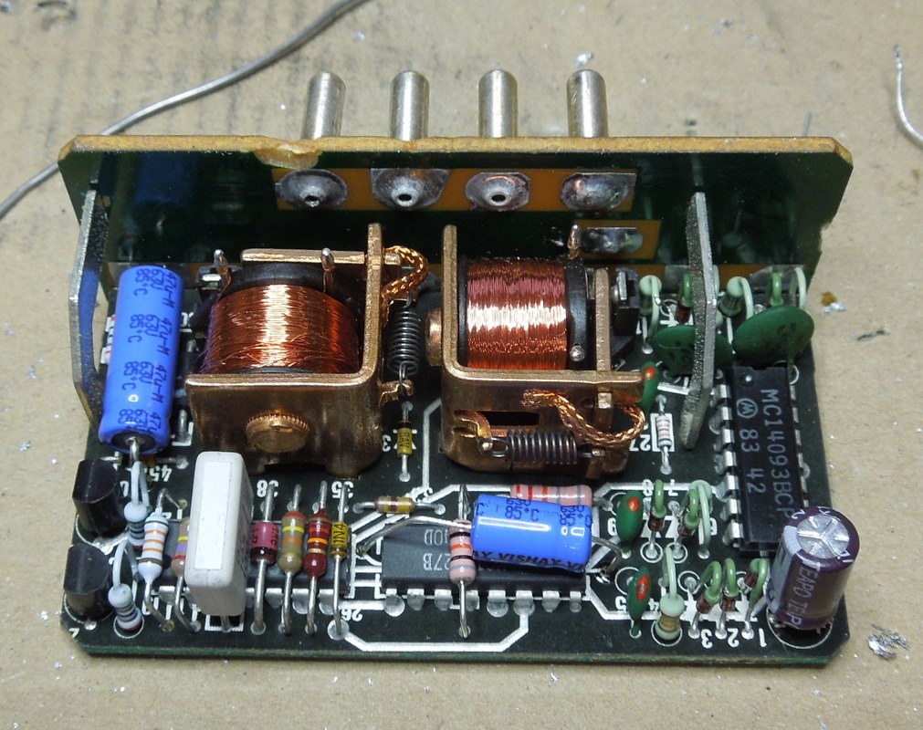
While testing the harness, I opened the seat heating relais, because one of the pins was wobbly. I could resolder that and while doing that I saw, that there were three electrolytic capacitors. So similar to the clock and the cruise control unit I thought it's a good idea to change them after nearly 40 years.
Two 22uF (one radial, one axial) and one 47uF … see pictures. In case you aren't aware, you have to careful with the polarity, so don't mix plus and minus ;-)
Surprise, surprise … it still worked!

ABS connectors
23 March 2020
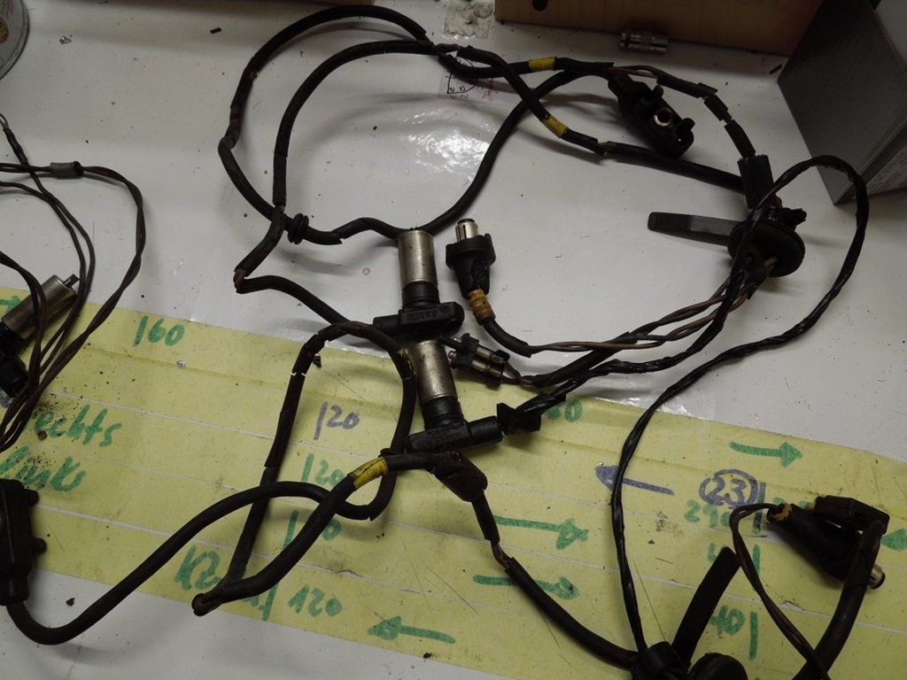
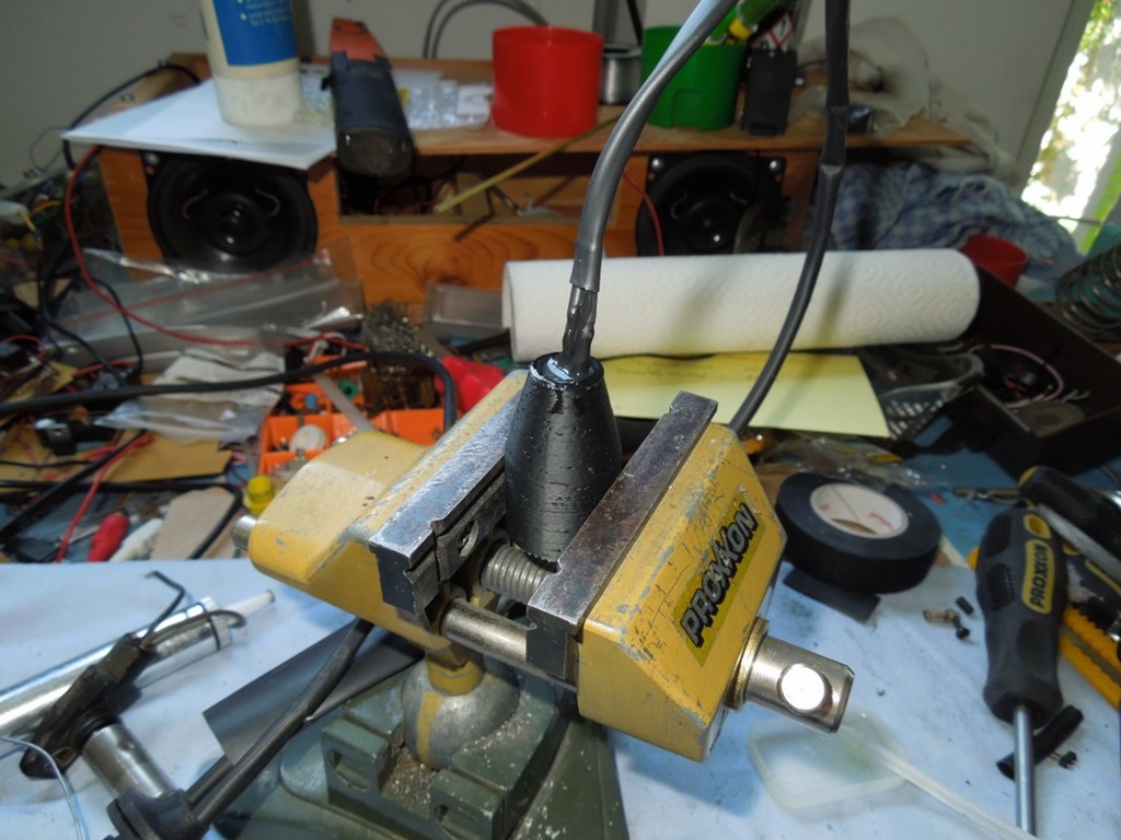
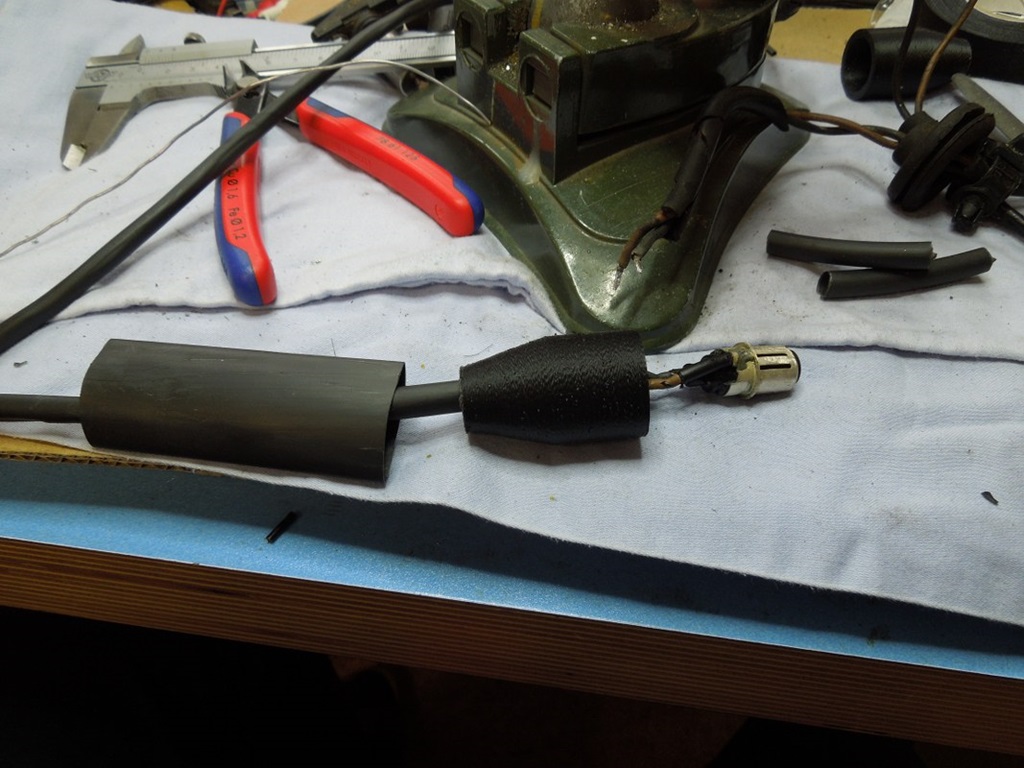
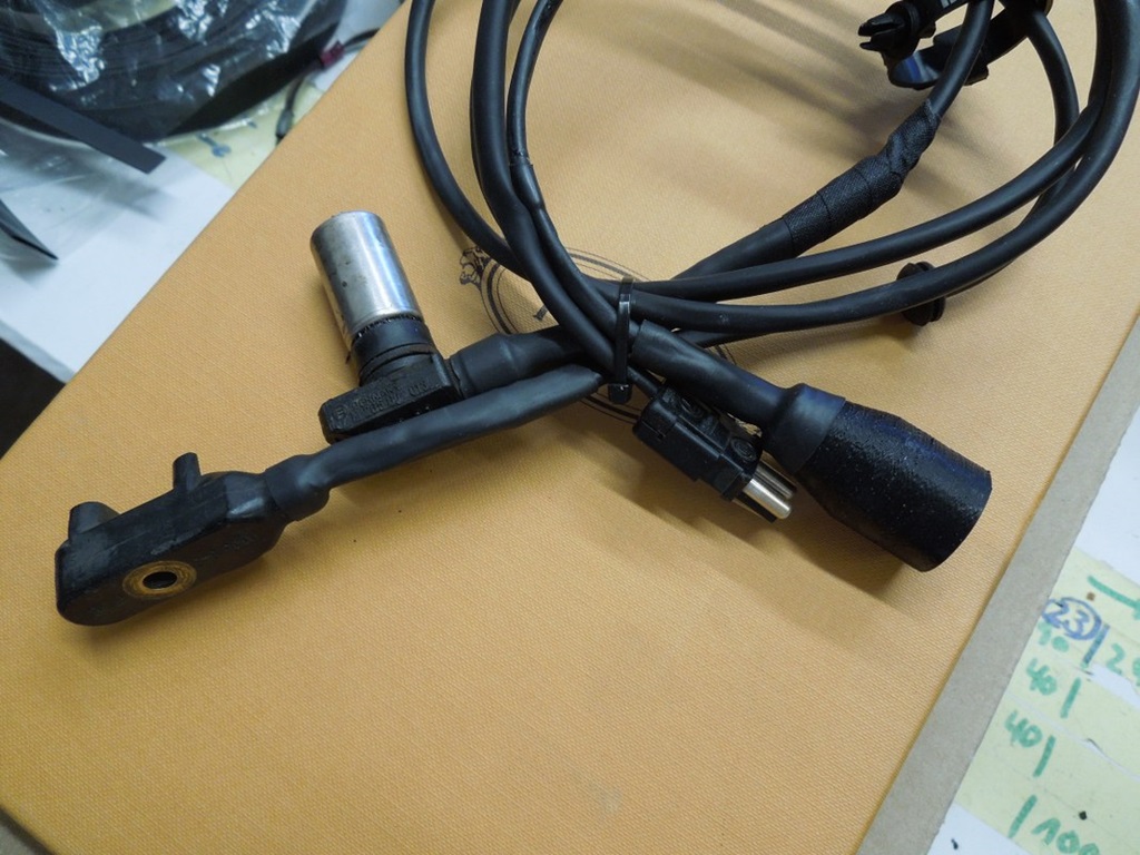
After Stefan took the axles apart, I finally had the ABS and brake pad wear indicator cables in hand. Both were totally brittle and hard.
I cut off the connectors and rewired them. For better protection I put two shrinking hoses around, new grommets and tried to make it look nicely.
However, the ABS (cinch) plug was brittle too, so it fell apart. So I got the idea to 3D-print the casing myself. The original cinch-plug fits in, but has to be glued in. Therefore it is firmly fixed AND sealed in one go. So both cables look fine and they should hopefully work!


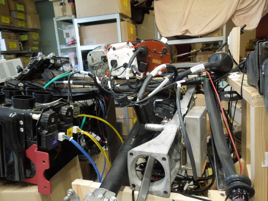
Complete harness finished ...
22 April 2020
So, I finally finished the - complete new - harness. Everything tested, but last Monday Juergen from Mercedes popped in and we tested it all again together with a 30A power supply. Some parts couldn't be tested (e. g. ABS control unit, motor related wiring), but I guess I managed 80-90%.
Well Juergen is not a man of many words, but he used the words "respect", "looks good" and that it was a pretty smart solution ("Du bist ein Fuchs"). I guess this is the maximum of compliments in his repertoire ;-) ... so that makes me pretty proud!
Harness testing ...
23 April 2020
So why did I do all this effort with the mockup? To test, test and test. Here's two "amateur" videos (I'm not into that) to show some examples what I tested. The harness is dismantled now and I do hope, that I have significantly less problems when the stuff is in the car.
Part I: Overview
Part II: Testing
Battery frame solution ...
27 November 2020
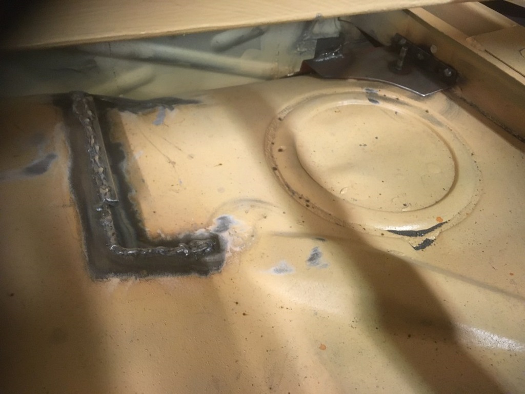
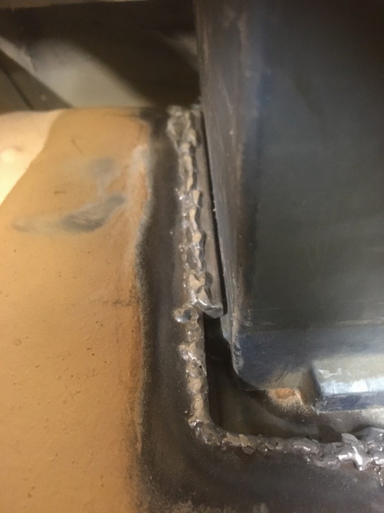
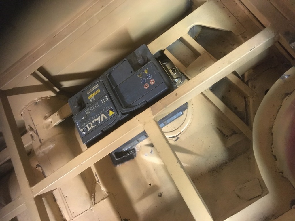
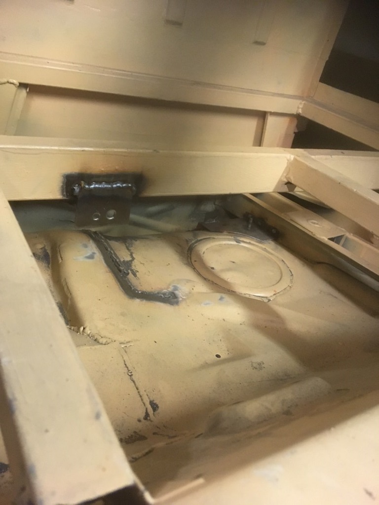
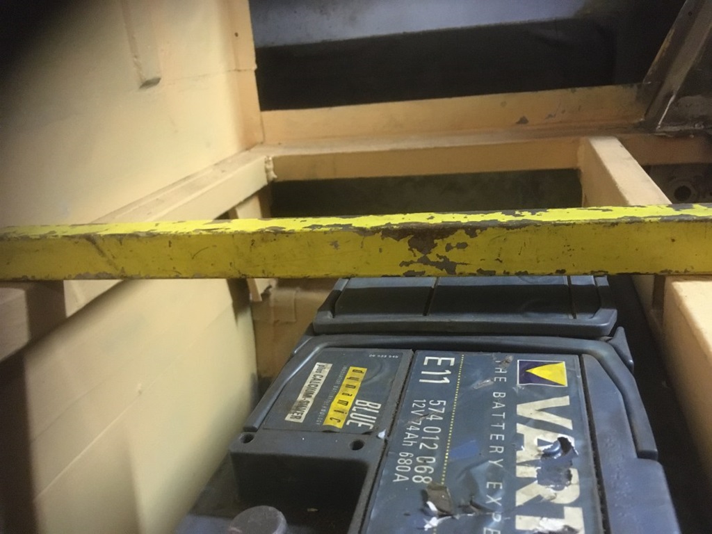
Timo has found a really clever solution for the battery holder. The area (on the right side) behind the passenger cabin was flattened a bit and he created two holders to reduce height compared to a "standard" battery frame.
This is imho extra smart as it is so simple. The battery is held by one bracket and a screw, it fits perfectly underneath the cargo area, clears safely the cargo covers ... fantastic!

Electrics behind the glove compartment ...
10 October 2021
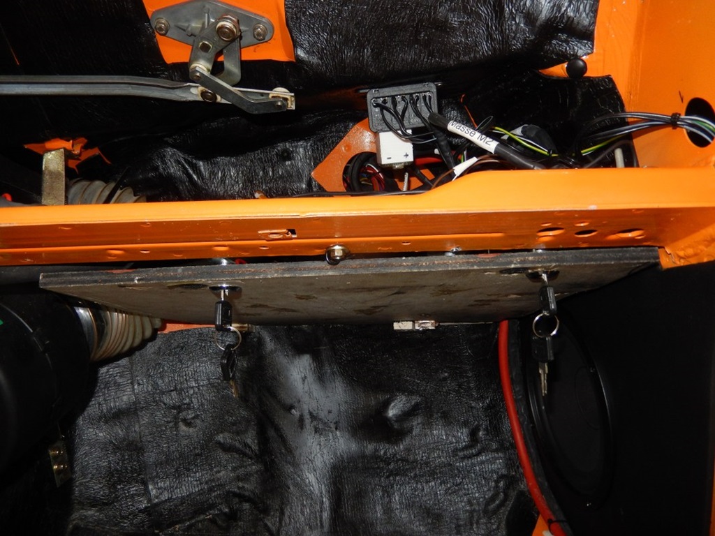
This is just to show, how the electrics behind the glove compartment finally turned out. The wooden plate just lies on two metal pieces on the firewall. In the front area I installed two "letter box locks"; you turn them 90° and the plate falls down (held by a little chain). Those locks - when locked - click into the dashboard cross bar and hold the hole wooden plate firmly.
The plate itself is now covered (underneath, not yet on the photos) with some leather. All in all it is quite practical to have it all in one place (except the stuff behind the centre console).
Was it worth the effort?
28 February 2022
As the car is reassembled now, I can tell you the final outcome: Yes, it was worth the effort, the harness was very good (even the ABS plug was correct), however not 100%, I made two mistakes:
1) With the brake pad sensors cable it IS important to check polarity ;-) ... I just put the pins in the socket ... not good ... took a while to find the fault (sensor is connected to ground within the brakes)
2) The other mistake I just couldn't know. I used a wiring diagram from a 1982 R107; however the horn wiring logic changed around 1980. So everytime I tested the horn, the fuse blew. Why? From around 1980 on the +12V were at the steering wheel and you switched the +12V to the horns by pressing the steering wheel. Before that, the +12V were connected to the horns and you switched ground ... logic explanation, but you might guess it took a while to find the reason
Bottom Line:
1) It was worth the effort. Imho you cannot successfully make such a conversion without proper 100% electrics.
2) Especially drawing ALL (!) cables in a proper wiring diagram proved useful (do it in colour!). Those original A3 b/w wiring diagrams from Mercedes are just useless. It was THE help when putting the car back together and trying to find faults.
3) Check the original Mercedes wiring diagram with the reality of your car. I found mistakes in the diagram as well as in the harness of the car. Write down EVERY bloody cable.
4) Testing, testing, testing. It proved useful to have that "test bench"; at least 80-90% you can pre-test. For example, I put the harness into the final car, only tested for a possible shortcut and the motor started rightaway.