Digital Gear Display
31 October 2017
How to display gears?
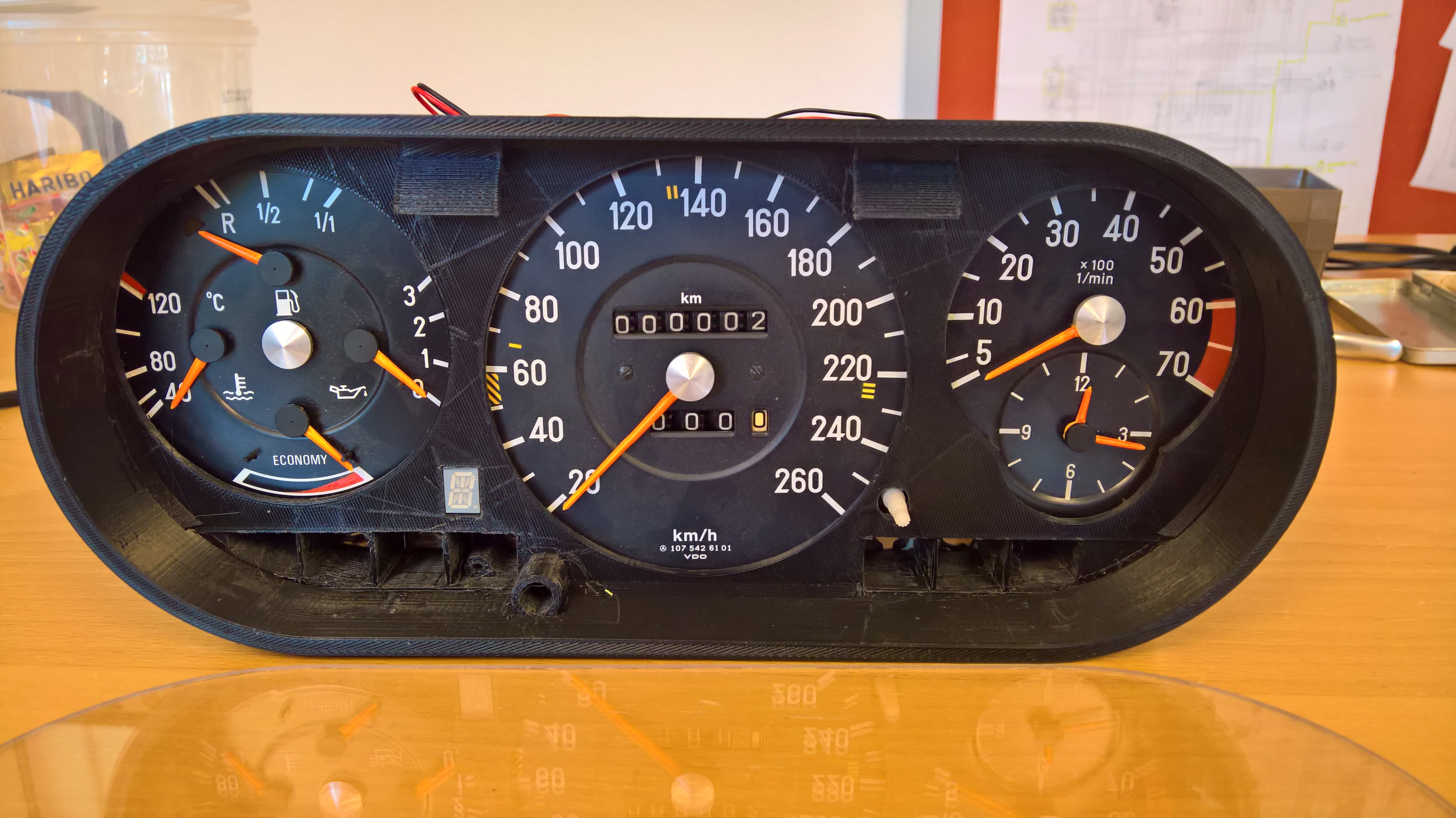
As you could see in the section "Cluster", there's just not enough room to integrate one of the original "Gear Displays" in the crowded cluster.
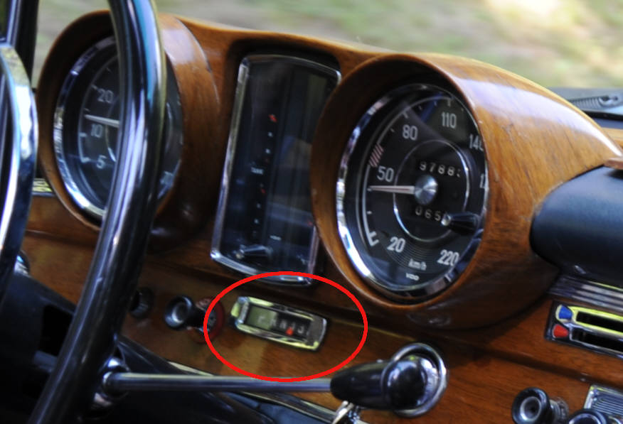
There's no room in the Dashboard itself (like on the photo here) and in the cluster (as it was original with the W114/W115) it isn't possible either.
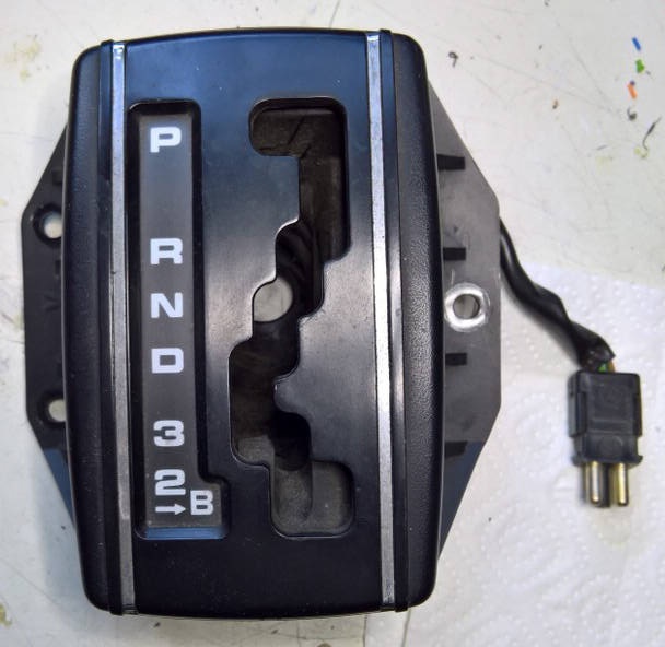
This "Display" was integrated when you ordered column shift to show the driver which gear was selected. This was operated by a mechanical wire connected to the column shift. So when the column shift was operated, the wire moved a little red arrow from left to right to show P, R, N, D, 3, 2.
How the display-gear-problem was solved
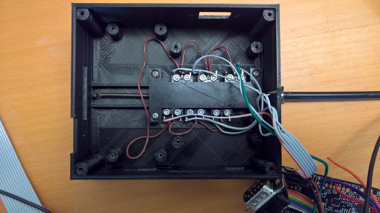
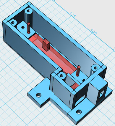
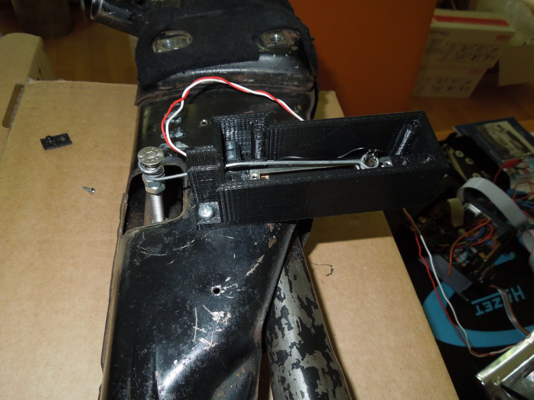
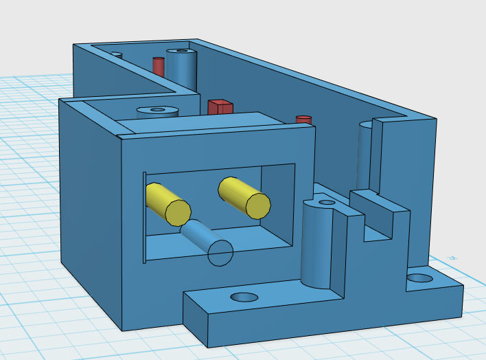
Well my idea was to stick to the "mechanical wire operation". However instead of moving a little arrow, I came up with a solution to connect this wire to a little "slider", which would operate seven micro Switches for P, R, N, D, 3, 2. The end of this slider is connected to a spring, so it moves back when shifting back to P.
The slider itself is connected to a simple "bicycle-brake-wire", which will be connected to the column shift in the car.
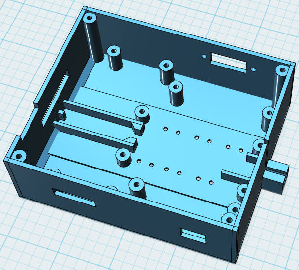
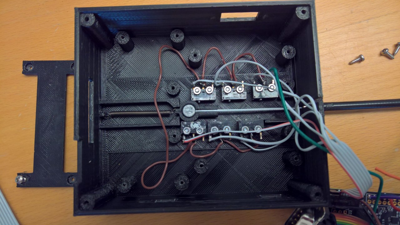
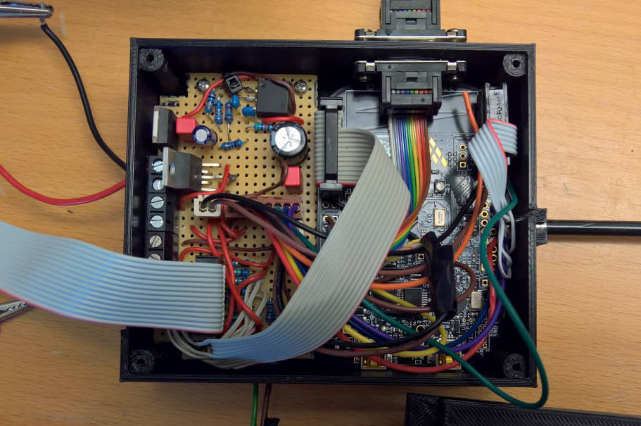
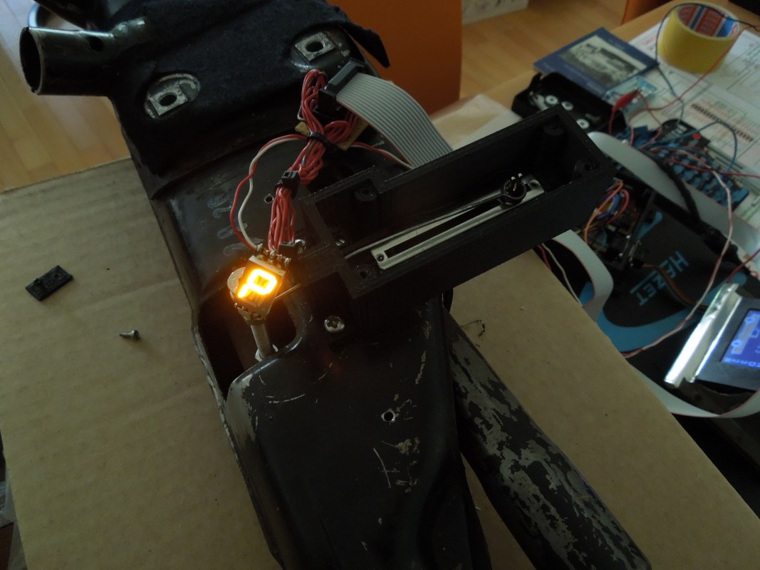
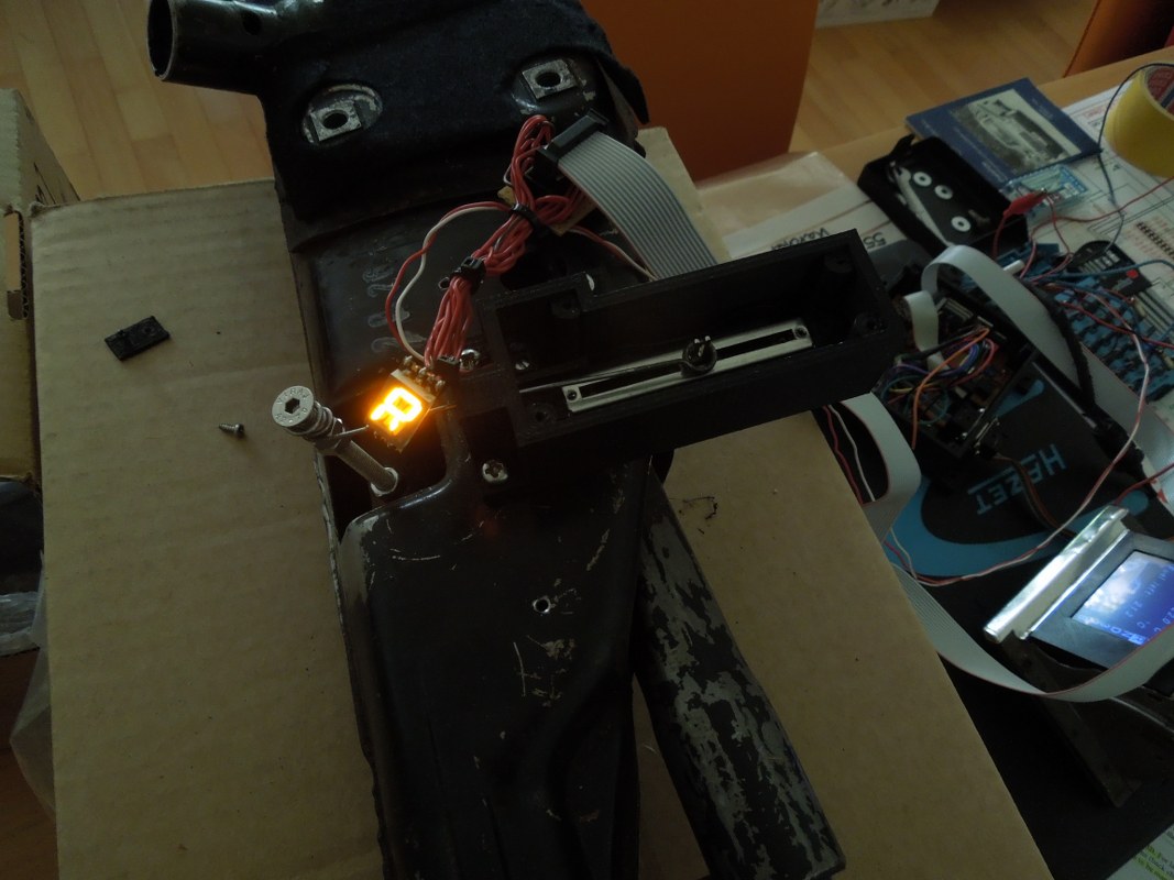
The slider and the micro-switches are covered by another plastic piece, printed in 3D. On top of that, an electronic circuit board and a microcontroller (KL25Z) is mounted. One of the functions of the microcontroller is to display the selected gear.
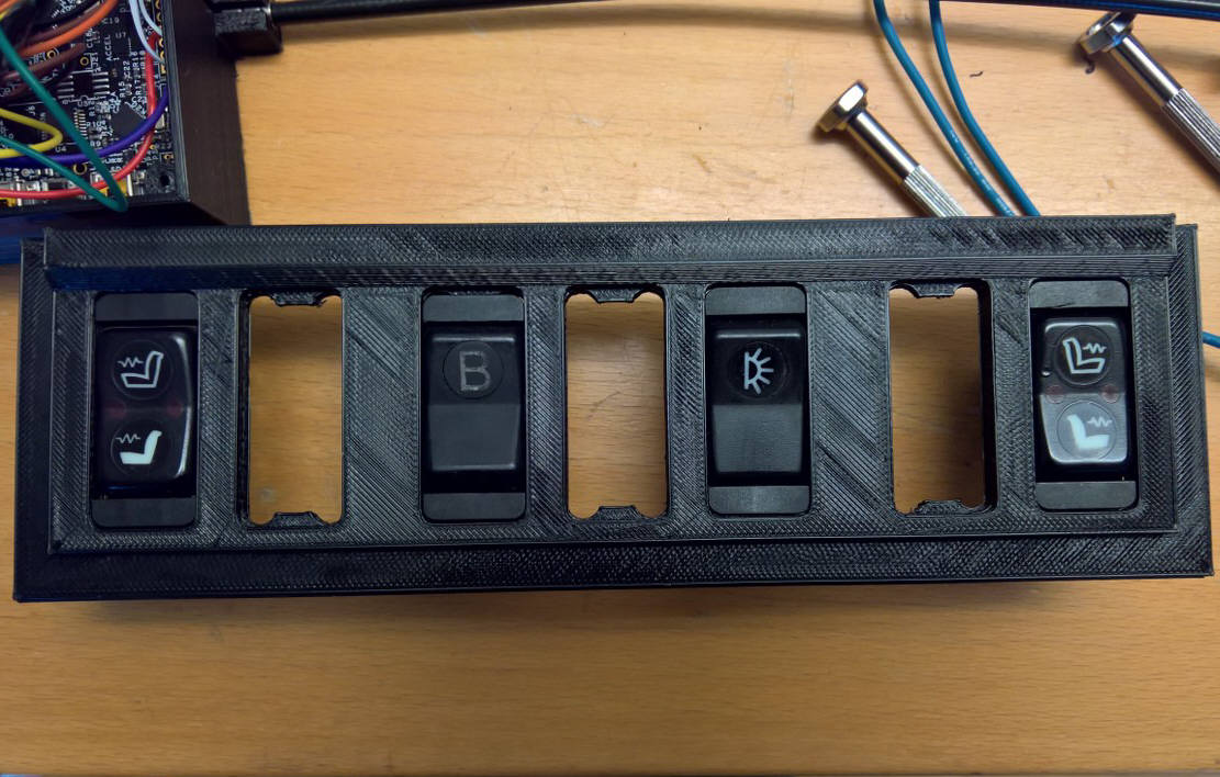
How the "B"-problem was solved
As some of you might know, from around 1981 on (maybe a bit earlier), the floor shift of the 4-speed-automatic changed and another position "B" was introduced. Before that P-R-N-D-3-2 was all. The "B"-Position forced the gearbox to shift into the first gear, e. g. when you tow a trailer or up steep mountains. That's where the "B" comes from, i. e. "Berg" (mountain).
However, as you can see on the Picture, the B-Position of the gear stick didn't change anything at the gearbox itself, it actually operated an electrical switch. This switch was connected to the gearbox Control.
My idea was to integrate a "new" "B"-switch somewhere in the Dashboard. The microcontroller should decided, under which conditions the B-Switch of the gearbox control is set or not (as an Output).
So what was the Task? In the floor shift it was impossible to activate the B-Switch without being in the "2"-position. This led to the following requirements:
- Whenever the gear is NOT in "2" you must not activate the B-Output for the gearbox Control
- When the Driver activates the B-Switch in P, R, N, D, 3 -> nothing must happen
- The B-Output should only be activated when the gear is in "2"
- If the gear is moved from 2->3 the B-Output should be automatically deactivated
So I converted a Switch for the heated windscreen (on/off) to a "Dashboard-B-Switch". This will be connected to the microcontroller. Another connection is from the microcontroller to the Gearbox-Control (B-Output), which will activate "B" for the car.
Quite a bit of Software written (C++) and it works!
Some other functions of the microcontroller I will explain later on ...
Digital Gear Display (II)
24 June 2018
New strategy re sensors ...
As I tried before to "get the gears" with either micro-switches or optical sensors, it turned out not to be reliable. So after some fiddling around, I came up with another solution:
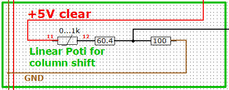
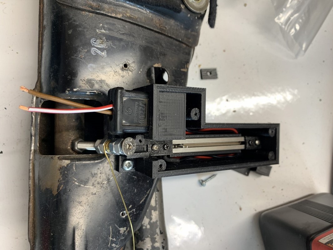
Instead of trying to get the exact position, I connected the gear lever to a linear potentiometer. This was done with a spare wire I had from the heating control conversion.
So every gear position represents a resistor value. This works as an analog input to the microcontroller, i. e. a voltage divider. I used a 1kOHM linear potentionmeter and with the software I can read the percentage of the input voltage. So what I will do at the car is to measure the %-value in e. g. "P"-Position and then "R"-Position. In the software I will take the median between those two; if the value is below that value, it will be "P", otherwise "R" (i. e. a threshold) and so on...
The advantage is, that if the mechanical connection lever-gearbox changes, I only have to do a software change (the threshold parameters from above).
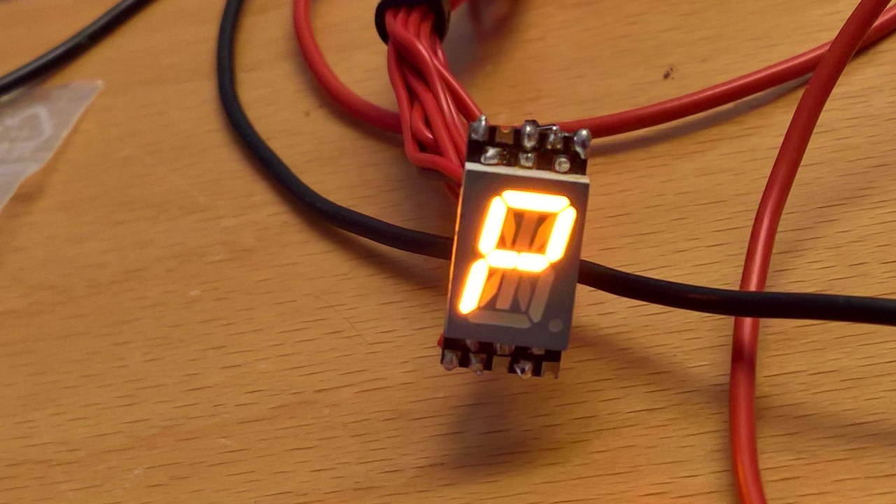
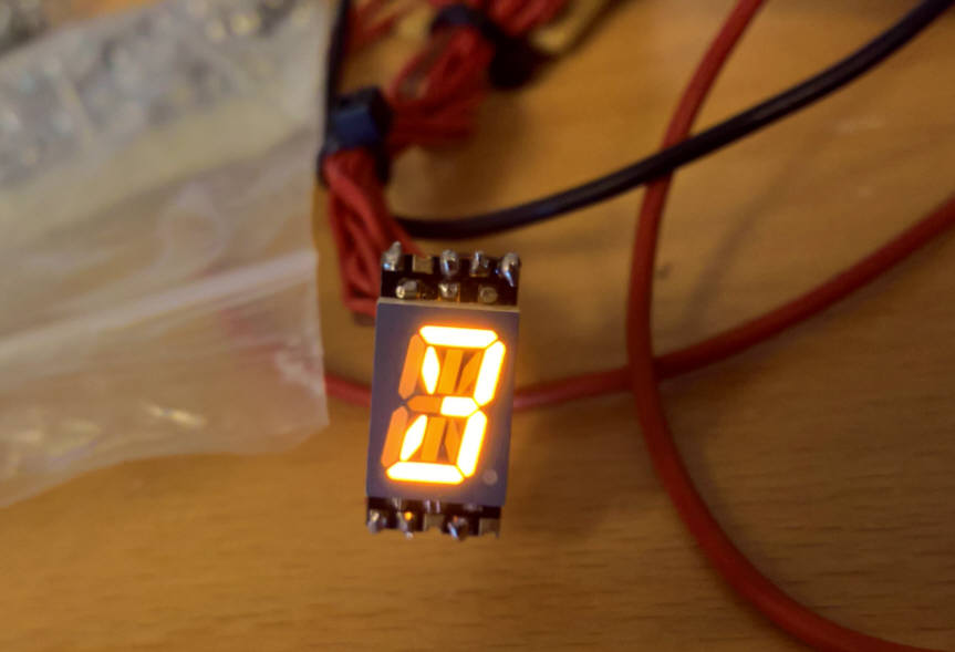
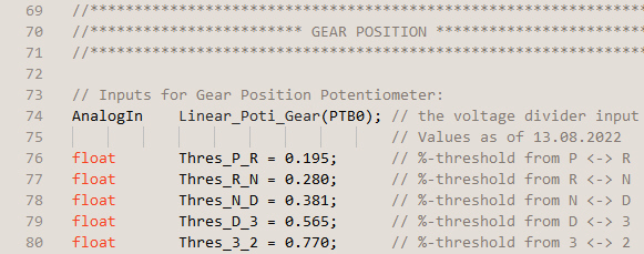
In the software there are five parametres, which represent the thresholds between the gears. The ashtray display is used to show the actual percentage (percent of the reference voltage) when you move the gearstick up and down.
So in case, there is any change within the gearbox etc., I just go through all the gears, note the new values for P, R, ... and put the new thresholds into the software ... compile, download and voilà!
 Threshold parametres ...
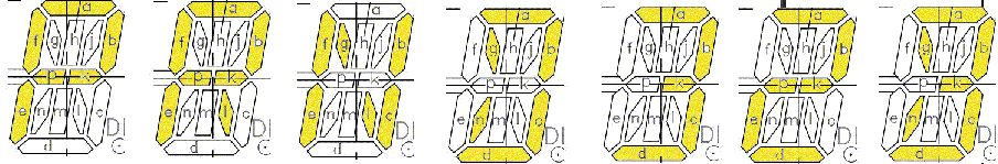 14 segment LED display ...
Digital Gear Display (III)
1 April 2019
Very special fine tuning ;-) ...
While working on the column shift details and restoring the whole thing, I had another idea of how to connect that poti to the car. Why not design the "female" part in the housing in a way, that a standard Mercedes plug fits? ;-)
… well it worked out! This might also serve as a reference in case I have to print some of those plugs myself … another example of useless engineering … but doesn't that apply for the whole project? ;-)
OBD Interface in action ;-)
20 February 2023
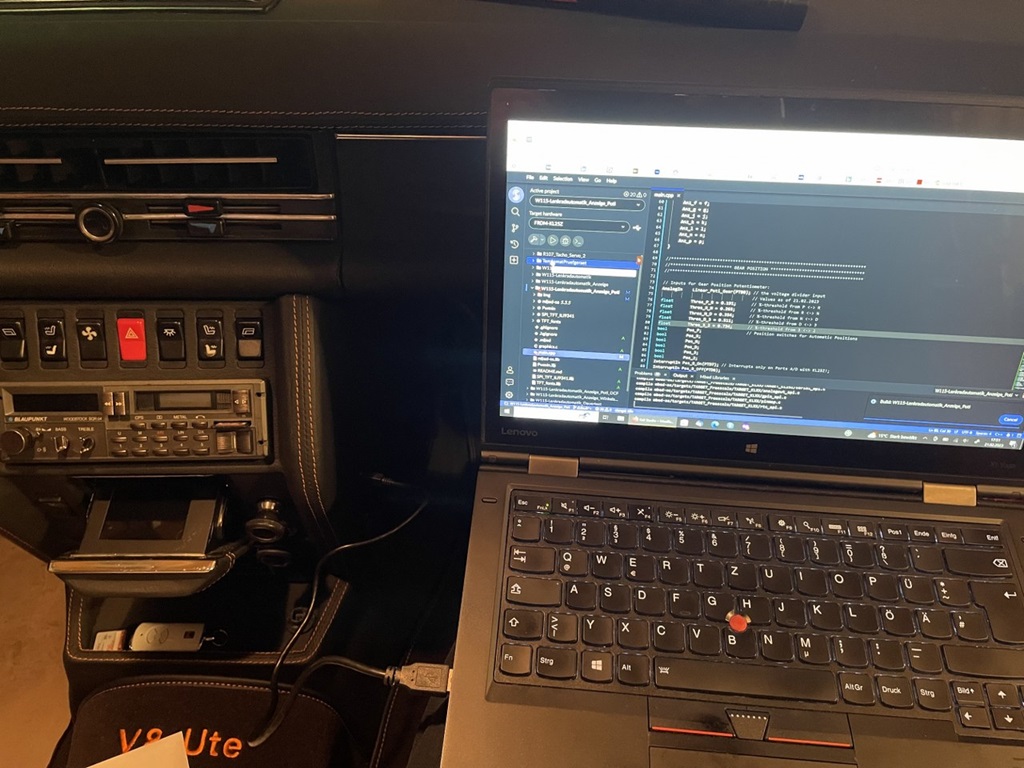
As mentioned here, the original "centre console bulb" was redesigned as my "OBD" interface for the electronic board. After changing the gearbox (described here), the values had to be readjusted. What's needed?
First you put the ignition on "1" and note all %-values (on the ashtray display) in all gear stick settings, from P to 2. The new values are entered into the software, compiler runs and you transfer the new software onto the board!
 OBD in action!